 .
.Parts of the Projector: Names and Functions
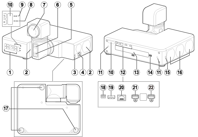
AControl panel
BIntake vents
CHDMI 3 connector
DPower connector
EArm latch release
FHead latch release
GLens
HStatus lamp
ITemperature warning lamp
JRemote receivers
KScrew holes for attaching stands
LInterface (connector) panel
MModel number plate (laser warning sticker)
NSpeaker
OSecurity slot*
PExhaust vents
QAdjustable feet
RService connector
SUSB connector (5 V DC power supply)
THDBaseT/LAN connector
UHDMI 1 connector
VHDMI 2 connector
* Compatible with Kensington MicroSaver security system locks.
Control Panel
Basic operations are performed using the control panel. The names and functions of the buttons on the control panel are given below.
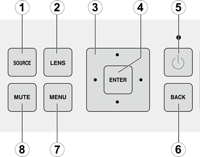
bTIP
Buttons C–H are duplicated on the remote control.
A The SOURCE Button
The input source changes each time the button is pressed.
| Input source | |||
|---|---|---|---|
| HDMI 1 | HDMI 2 | HDMI 3 | HDBaseT |
B The LENS Button
The selected function changes each time the button is pressed.
| Lens function | |||
|---|---|---|---|
| H-SHIFT&V-SHIFT | FOCUS | ZOOM | |
C The Selector (e/f/g/h)
Navigate the menus.
D The ENTER Button
Select items highlighted in the menus.
E The Power Button
Turn the projector on or switch it to standby.
F The BACK Button
Return to the previous menu.
G The MENU Button
Display the menus used to adjust projector settings.
H The MUTE Button
Temporarily suspend projection and mute audio. Audio can be restored by pressing any other button or by pressing the MUTE button again.
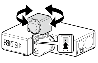
Latch Releases
Before rotating the lens, release the latches by pressing the arm (A) and head (B) latch releases.
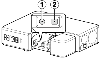
bTIPS
- The latches will re-engage automatically if not manually re-engaged within 10 seconds.
- The LED lights while the head latch is released.
dCAUTION
This projector features a rotating lens. The latch that protects the lens must be released before the lens can be rotated.
The Arm Latch Release
When the arm latch is disengaged by pressing the arm latch release, the arm can be rotated 90° in the direction shown.
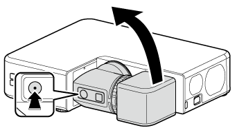
bTIP
When the projector is oriented vertically, the arm can also be rotated 90° in the other direction.
The Head Latch Release
When the head latch is disengaged by pressing the head latch release, the projector head can be rotated 360° in 90° increments.
dCAUTIONS
- Some portions of the projected image may not be visible depending on lens shift and the orientation of the lens.
- When rotating the lens, keep it supported and rotate it slowly.
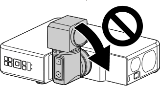
-
To protect the lens, the arm locks to prevent it rotating in the direction shown when the projector head is oriented as shown in the illustration.
Connectors
Connect devices via the appropriate connector.
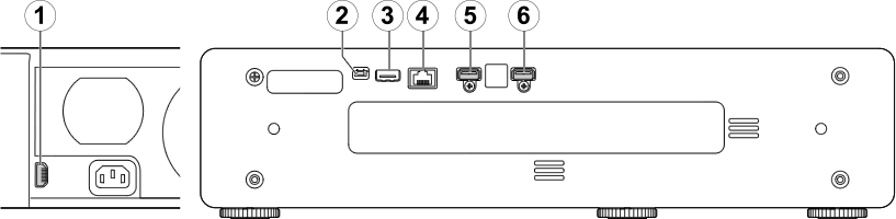
A HDMI3/E HDMI1/F HDMI2
HDMI devices can be connected via the projector's HDMI 1, HDMI 2, and HDMI 3 connectors.
dCAUTIONS
- Switch the projector to standby and confirm that the HDMI device is either off or in standby mode before connecting the cable. After connecting the cable to both devices, turn the projector on first and then turn on the HDMI device.
- Some devices require an adapter and/or a dedicated cable.
bTIP
Use the HDMI 3 connector when the projector is in vertical orientation.
B The Service Connector
Fujifilm-authorized technicians use the service connector for inspection and repair.
C The USB Connector
Use for the supply of DC 5V 1.5A power.
D The HDBaseT/LAN Connector
Third-party video transmitters that support HDBaseT can be connected via the projector's HDBaseT/LAN (RJ45) connector.
dCAUTIONS
- Use an STP LAN cable with category 5e shielding or better.
- The maximum distance that video can be transmitted over a LAN cable is 100 m (328 ft).
- Operation is not guaranteed with all HDBaseT-compatible devices or in all operating environments.
- The projector cannot be connected directly to networks operated by mobile communications service providers, fixed-network communications service providers, Internet service providers, or other telecommunications carriers. Any connection to the Internet must be made via a router.
Indicator Lamps
Projector status is shown by whether the POWER (A), TEMP (B), and STATUS (C) indicator lamps are on, flashing, or off.
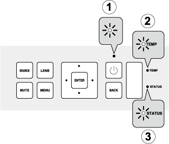
The statuses shown by the condition of the indicator lamps are listed below.
| Lamp | |||
|---|---|---|---|
| Power | TEMP | STATUS | Projector status |
| On (amber) | Off | Off | Projector in standby mode. |
| Flashing (amber) | Off | Off | Projector in standby mode (network standby). |
| On (white) | Off | Off | Projector on. |
| On (white) | Flashing (amber) | Off | Projector temperature elevated. |
| On (white) | On (amber) | Off | Laser temperature elevated. |
| Off or on (white) | Off | On (amber) or flashing (amber) | Problem with cooling fan. |
| Flashing (white) | Off | Flashing (amber) | Problem with optical engine. |
| Flashing (white) | Off | On (amber) | Problem with power supply. |