
 .
.Part Names and Functions
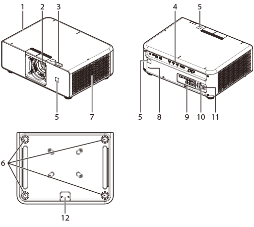
| No. | Name |
|---|---|
| 1 | Intake vents |
| 2 | Lens Mounting Section |
| 3 | Indicator Lamps |
| 4 | Connectors |
| 5 | Remote receiver |
| 6 | Adjustable feet |
| No. | Name |
|---|---|
| 7 | Exhaust vent |
| 8 | MicroSaver Security System® PIN Slot |
| 9 | Control panel |
| 10 | Power connector |
| 11 | Main power |
| 12 | Security lock |
Control panel
Basic operations are performed using the control panel. The names and functions of the buttons on the control panel are given below.
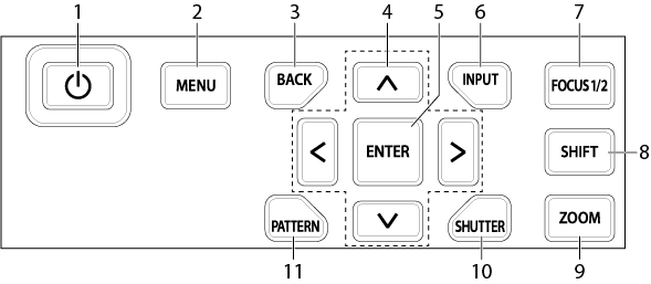
| No. | Button Name | Description |
|---|---|---|
| 1 |  (Power) (Power) |
Turns the unit on or puts it in standby mode. |
| 2 | MENU | Displays the menu screen for various settings and adjustments. |
| 3 | BACK | Returns to the previous menu level during menu operation. |
| 4 | ▲▼◀▶ (Selector) | Used for menu operation. |
| 5 | ENTER | Confirms the item selected during menu operation. |
| 6 | Input | Switches between input devices. |
| 7 | FOCUS1/2 | Switch between FOCUS1/2 to adjust the focus. |
| 8 | Shift | Adjusts lens shift. |
| 9 | ZOOM | Adjusts lens zoom. |
| 10 | SHUTTER | Temporarily mutes the image and audio. Press the button again to resume projection. |
| 11 | TEST PATTERN | Display a Test Pattern and switch between patterns using the ◀▶ arrow keys. |
Connectors
Connect the cables to the appropriate connection terminals for the devices being connected.
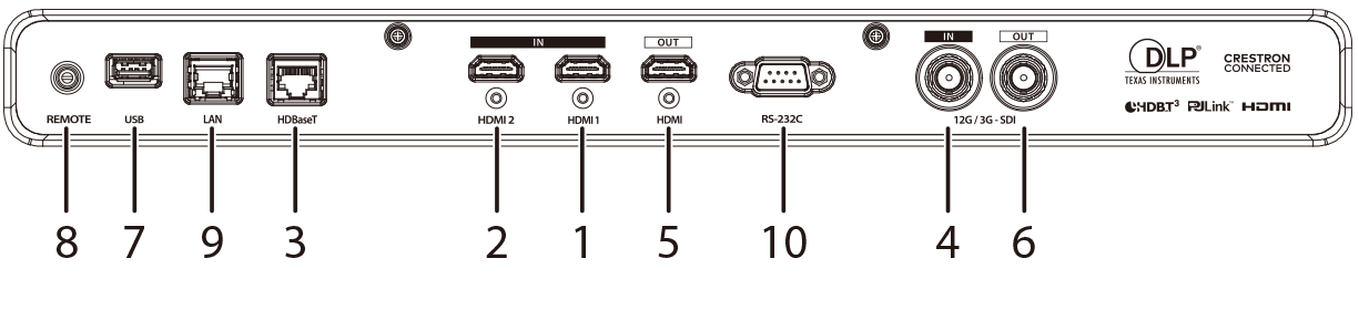
| Connection Name | Description | |||
|---|---|---|---|---|
| VIDEO IN | 1 | HDMI® 1 | Type A | HDMI® 2.0, HDCP 2.3 compliant |
| 2 | HDMI® 2 | Type A | HDMI® 2.0, HDCP 2.3 compliant | |
| 3 | HDBaseT | RJ-45 | HDBaseT™ 3.0 compliant | |
| 4 | 12G/3G-SDI |
BNC | 12G/3G SDI compatible | |
| VIDEO OUT | 5 | HDMI® | Type A | HDMI® 2.0, HDCP 2.3 compliant |
| 6 | 12G/3G-SDI | BNC | 12G/3G SDI compatible | |
| For control | 8 | REMOTE | 3.5mm stereo mini jack |
For remote control (wired) |
| 9 | LAN | RJ-45 | For network connection, 10Base-T/100Base-TX | |
| 3 | HDBaseT | RJ-45 | For projector control | |
| 10 | RS-232 | D-Sub 9-pin male | For projector control | |
| OTHER | 7 | USB | Type A | DC 5V 2A (maximum) power supply, for maintenance |
d Caution
- Before connecting, ensure that this unit and all connected devices are in standby mode. After all connections are complete, turn on this unit first, and then turn on the connected devices.
- Depending on the device, a dedicated cable, conversion plug, or adapter may be required.
Indicator Lamps
The projector status can be determined by the lit, flashing, or off states of the indicator lamps (ON/STANDBY, TEMP, STATUS).
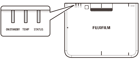
The indicator lamp patterns and the corresponding projector status are as follows.
| Lamp | |||
|---|---|---|---|
| ON/STANDBY | TEMP | STATUS | Projector status |
| RedSteady | - | - | Standby state (Standby) |
| GreenFlashing 1 | - | - | Starting up |
| GreenSteady | - | - | POWER ON |
| RedFlashing 1 | - | - | Standby state (Network Standby) |
| - | ☀OrangeFlashing 1 | - | Shutting down |
| GreenSteady | GreenSteady | - | shutter function on |
| - | GreenFlashing 2 | - | Communicating |
| - | ☀OrangeGreen Flashing 3 |
- | Firmware update in progress |
| GreenSteady | GreenSteady | GreenSteady | Firmware update starting |
| ☀OrangeFlashing 1 | ☀OrangeFlashing 1 | - |
Firmware update standby |
| RedSteady | GreenSteady | - |
Factory Reset |
| GreenSteady | RedFlashing 1 | ☀OrangeFlashing 1 | Main unit temperature rise |
| GreenFlashing 2 | - | ☀OrangeFlashing 2 | Laser light source error |
| GreenFlashing 2 | RedFlashing 1 | ☀OrangeFlashing 2 | DMD Error |
| - | - | ☀OrangeSteady | Fan 1 Error |
| - | - | ☀OrangeFlashing 1 | Fan 2 Error |
| - | - | ☀OrangeFlashing 2 | Fan 3 Error |
| GreenSteady | - | ☀OrangeSteady | Fan 4 Error |
| GreenSteady | - | ☀OrangeFlashing 1 | Fan 5 Error |
| - | RedSteady | ☀OrangeSteady | Fan 8 Error |
| - | RedSteady | ☀OrangeFlashing 1 | Fan 9 Error |
| - | RedSteady | ☀OrangeFlashing 2 | Fan 10 Error |
| GreenFlashing 1 | RedSteady | - | Fan 11 Error |
| GreenFlashing 1 | - | ☀OrangeFlashing 1 | Filter wheel Error |
| GreenFlashing 1 | - | ☀OrangeFlashing 2 | phosphor wheel error |
| ☀OrangeSteady | - | ☀OrangeSteady | Power error |
b Note
The LED indicator supports three flashing modes:
- Flashing 1: Flashes once every 0.5 s.
- Flashing 2: Flashes once every 0.04 s.
- Flashing 3: Two colors alternate every 0.5 s.
- "If error occur, please contact the place of purchase."