.
.Lens
Depending on the projection lens used, lens adapter mounting and removal may be required.
For details, refer to a“Lens Adapter.”
Available projection lenses
| Model name | 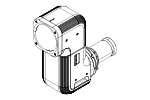 FP-ZL034 FP-ZL034 |
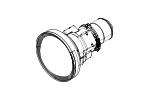 FP-ZL050 FP-ZL050 |
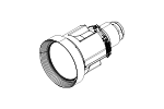 FP-ZL125 FP-ZL125 |
| lens adapter | Required | N/A | N/A |
| Lens Shift | Motorized: V (vertical) ±60%, H (horizontal) ±30% | Motorized: V (vertical) ±53%, H (horizontal) ±25% | Motorized: V (vertical) ±55%, H (horizontal) ±25% |
| ZOOM | Motorized: 1.0x–1.2x | Motorized: 1.0x–1.3x | motorized zoom: 1.0x–1.6x |
| TR value*1 | 0.34 (wide end)–0.41 (tele end) | 0.50 (wide end)–0.65 (tele end) | 1.25 (wide end)–2.0 (tele end) |
| F-number | F2.2 (wide end) – F2.41 (tele end) | F2.0 (wide end) – F2.2 (tele end) | F2.0 (wide end) - F2.33 (tele end) |
| External dimensions | Width 128 × Length 341 mm | ø164 × 247 mm (length) | ø138 × 217 mm (length) |
| Weight | Approx. 4.5 kg | Approx. 2.3 kg | Approx. 1.9 kg |
The TR (throw ratio) value is calculated by dividing the projection distance by the screen width.
- Attaching and Removing the FP-ZL034 Projection Lens
- Attaching and Removing the FP-ZL050/FP-ZL125 Projection Lens
Attaching and Removing the FP-ZL034 Projection Lens
The ZP-ZL034 projection lens requires a lens adapter. Attach the lens adapter in advance.
For details, refer to a“Lens Adapter.”
Supported Mounting Directions
The FP-ZL034 projection lens can be attached to the lens adapter in two directions as shown in the figure below.
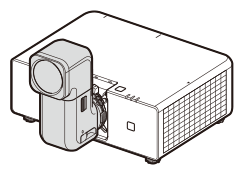
90 degrees
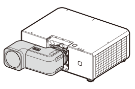
0 degrees
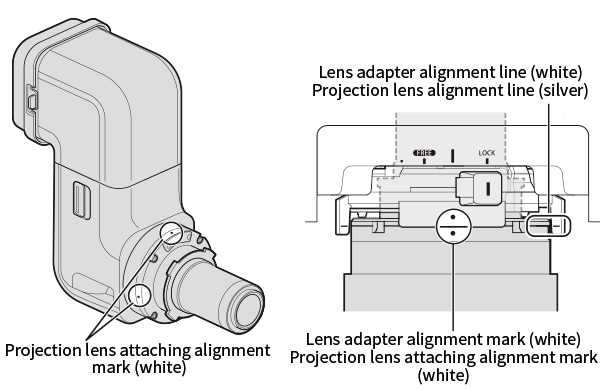
Regarding the mounting direction, the projection lens can only be mounted when the projection lens mounting indicator is aligned with the lens adapter mounting indicator.
d Caution
When mounting or removing the projection lens, hold it by the projection lens mount area. In particular, avoid holding the top of the FP-ZL034 bent-type projection lens. Failure to do so may cause lens damage.
Projection lens mounting
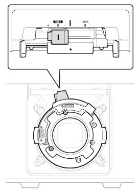
Before mounting, confirm that the lens adapter lever is in the FREE position and that the three lens adapter fixing screws are recessed behind the lens mounting surface (the screws should be tightened into the projector body).
-
Remove the projection lens rear cover, determine the desired mounting direction, and insert the lens straight into the projector body.
* Perform this with the lens front cover still attached.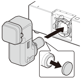
-
Confirm that the lens is inserted to the position where the lens adapter index line and the projection lens index line are aligned.
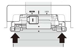
If the projection lens cannot be inserted up to the index line, the following may be the cause.
A. The lens adapter fixing screw is not tightened.
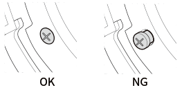
B. The projection lens is inserted in a direction other than the specified direction.
-
Move the lens adapter lever to the LOCK position.
* The lever will not move if the projection lens is not inserted correctly.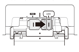
-
Mount the lens replacement cover.
Place the lens replacement cover on the projector body and press it in the direction of the arrow to mount it.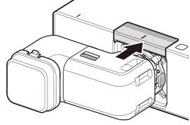
-
Remove the lens front cover.
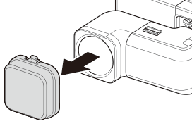
Removing the projection lens
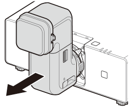
To remove the projection lens, follow the Mounting procedure in reverse.
-
Attach the lens front cover.
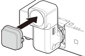
-
Move the lens adapter lever to the FREE position.
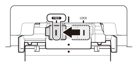
-
Pull out the projection lens.
lens axis lock lever
The FP-ZL034 projection lens is rotatable and equipped with a lock mechanism on the lens axis. Rotate it using the following procedure. Be sure to engage the lock during projection.
d Caution
- Vignetting may occur depending on the projection direction and lens shift adjustment.
- When rotating the lens, support the lens unit and rotate it slowly.
- When changing the lens orientation, pay close attention to the surroundings. If projected light enters the eyes, it may cause vision impairment or other injuries.
Sliding the lens axis lock lever to FREE to unlock it allows the lens unit to be rotated 360° in 90° increments around the lens axis. After rotating, be sure to set the lock lever to LOCK.
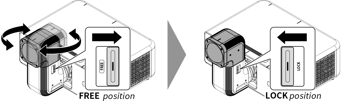
Setting the lens axis lock lever to FREE allows the lens to rotate, and setting it to LOCK engages the lock.
Precautions for transport
d Caution: When transporting the projector, be sure to hold it by its base. Do not hold it by the lens or the opening around the lens. Failure to observe this precaution could damage the product.
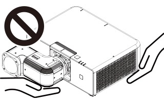
Attaching and removing the FP-ZL050/FP-ZL125 projection lens
The FP-ZL050/FP-ZL125 projection lens does not use a lens adapter. Remove the lens adapter in advance.
For details, refer to a“Lens Adapter.”
projection lens mounting
The projection lens can be mounted without removing the lens replacement cover.
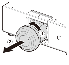
Remove the projection lens rear cover, align the surface marked TOP with the top surface of the projector body and insert it straight (A), then rotate the projection lens clockwise until it stops (B).
* Rotation should be approximately 35 degrees.
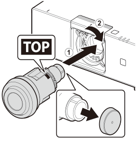
Removing the projection lens
To remove the projection lens, follow the Mounting procedure in reverse.
-
Attach the lens front cover.
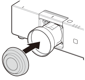
-
Rotate the projection lens counterclockwise until it stops (A), then pull out the projection lens (B).