.
.DISPLAY
Configure settings related to the projector DISPLAY.
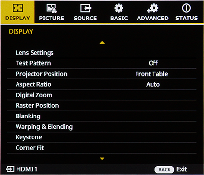
Lens Settings
Configure settings related to the Lens.
Select the desired Lens Settings item and press the ENTER button to display the settings screen.
| Item | Description |
|---|---|
| Lens Shift | Adjusts the projected image position by shifting the lens optical axis (Lens Shift). |
| Lens shift settings | Configure settings related to Lens Shift. |
| Lens Shift Memory | Save the Lens Shift Location. |
| Lens Motor Lock | When set to On, Lens Shift, Focus 1, Focus 2, and Zoom operations are disabled. |
| Focus 1 | Adjust overall screen focus for the projected PICTURE. |
| Focus 2 | Adjust focus at the screen periphery for the projected PICTURE. |
| ZOOM | Adjust the size of the projected image. |
 Lens Shift
Press the ENTER button to display the Lens Shift adjustment screen, and use the arrow (up/down/left/right) buttons to adjust the projected image position.
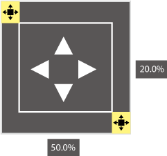
Lens shift settings
Configure settings related to Lens Shift.
Press the ENTER button to display the submenu, and select the desired setting item.
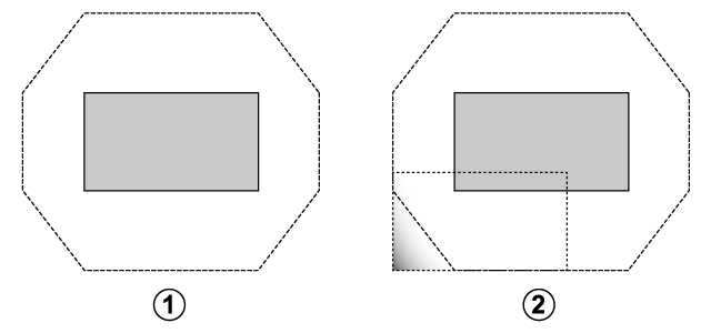
Shift area
Select the Lens Shift Shift Area.
| Setup | |
|---|---|
| Limited | Full |
-
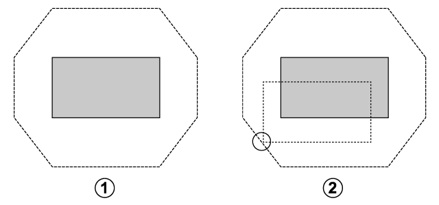
Limited: Limit: Shifts the lens within the range of full image visibility.
A Center Location
B No image cropping when Lens Shift is moved to the Bottom Left
-
Full: Shifts the Lens Shift Area to its maximum width.
A Center Location
B IMAGE is cropped when Lens Shift is moved to the Bottom Left
Home Position
Return the lens to the home position.
Press the ENTER button to display a confirmation screen for returning the lens to the home position.
Press OK to start lens shift. Do not perform other operations until the message displayed while the Lens is moving disappears.
Calibration
Perform lens calibration. When calibration is complete, a message appears prompting you to clear all lens shift memories.
Lens Shift Memory
Save up to five Lens Shift Location settings.
Press ENTER to display options and then select the desired item.
- Select Select Memory and press ENTER. Select the desired memory from Memory 1 through Memory 5 as needed.
- Select any of the following items:
- Load: Moves the lens to the Lens Shift position saved in the selected Memory.
- Save: Saves the current Lens Shift position to the selected Memory.
- Clear: Clears the contents of the selected Memory.
- Selecting All Clear will clear the contents of all memories.
b Note
- Calibration can also be performed by pressing and holding the SHIFT button on the remote control for 3 seconds or more.
- To ensure accurate data recording, perform Calibration when using Lens Shift Memory for the first time.
Lens Motor Lock
Lock or unlock lens motor.
| Setup | Description |
|---|---|
| Lock | Locks operations for Lens Shift, Focus 1, Focus 2, and Zoom. |
| Unlock | Enables Lens Shift, Focus 1, Focus 2, and Zoom operations. |
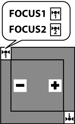
 Focus 1 /
  Focus 2
Adjust focus.
Press ENTER to display the focus dialog and use the selector (left or right ) to adjust focus.
- FOCUS1: Adjusts the optical axis center of the screen.
- FOCUS2: Adjusts the screen periphery.
Depending on the lens type, adjustments may be made using FOCUS1 only. For details, please refer to "Projection status adjustment" and "Focus adjustment."
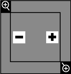
ZOOM
Adjust the size of the projected image.
"Press ENTER to display the zoom dialog and use the selector (up, down, left, and right) toadjust the size of the projected image."
Select “−” to decrease the projected IMAGE size and “+” to increase it.
TEST PATTERN
Choose a grid or other test pattern for display during installation.
| Setup | ||||||||||||||||
|---|---|---|---|---|---|---|---|---|---|---|---|---|---|---|---|---|
| Off | 1 | 2 | 3 | 4 | 5 | 6 | 7 | 8 | 9 | 10 | 11 | 12 | 13 | 14 | 15 | 16 |
Test Pattern 1

Test Pattern 2
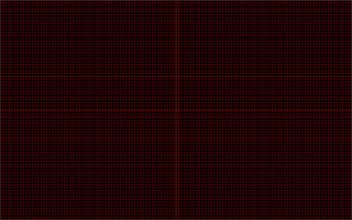
Test Pattern 3
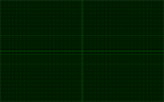
Test Pattern 4
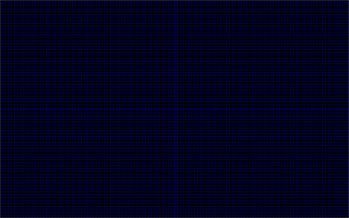
Test Pattern 5

Test Pattern 6

Test Pattern 7
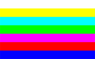
Test Pattern 8

Test Pattern 9

Test Pattern 10

Test Pattern 11

Test Pattern 12

Test Pattern 13

Test Pattern 14

Test Pattern 15

Test Pattern 16
b Note
To temporarily hide the menu screen while a Test Pattern is displayed, press the ON SCREEN button on the remote control. Press the ON SCREEN button again to display the menu.
Projector Position
Select the projection position according to the installation status of the projector.
| Setup | |||
|---|---|---|---|
| Front Table | Rear Table | Rear Ceiling | Front Ceiling |
-
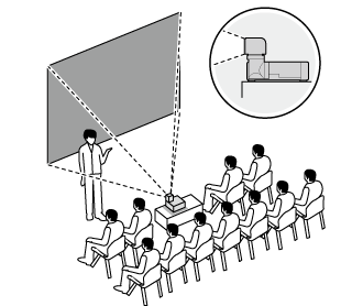
Front Table: Choose if the projector is placed on a table in front of the screen.
-
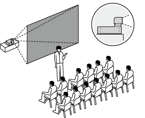
Rear Table: Choose if the projector is placed on a table behind the screen.
-
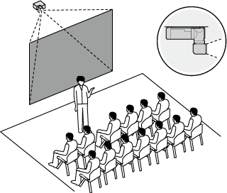
Rear Ceiling: Select when the projector is suspended from the ceiling to project from behind the screen.
-
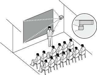
Front Ceiling: Select when the projector is suspended from the ceiling to project from the front of the screen.
Aspect Ratio
Position the beam according to the projector’s location.
| Setup | |||||
|---|---|---|---|---|---|
| Auto | Real | 4:3 | 16:10 | 16:9 | 21:9 |
b Note
The setting for each input is stored separately.
Digital Zoom
Zoom the projected image in using digital zoom.
Highlight digital zoom in the DISPLAY menu and press ENTER to show the options.
| Item | Description |
|---|---|
| Proportional | Resize the projected image proportionally. |
| Horizontal | Adjusts the horizontal magnification of the projected image. |
| Vertical | Adjusts the vertical magnification of the projected image. |
| Digital Shift | Shift the image digitally. |
| Reset | Reset digital zoom settings to the default values. |
Proportional
Set On to enable resizing the projected image proportionally or set Off to disable this function.
| Setup | |
|---|---|
| On | Off |
Horizontal
Adjusts the horizontal magnification of the projected image.
| Setup | |
|---|---|
| 50.00%~100.00%~400.00% | |
Vertical
Adjusts the vertical magnification of the projected image.
| Setup | |
|---|---|
| 50.00%~100.00%~400.00% | |
Digital Shift
Shift the projected image digitally by increasing the horizontal and vertical magnification.
| Setup | |
|---|---|
| Horizontal | 0.00~50.00~100.00 |
| Vertical | 0.00~50.00~100.00 |
Reset
Reset digital zoom settings to the default values.
| Setup | |
|---|---|
| Cancel | Reset |
Raster Position
Input images that do not fill the display can be positioned as desired within the screen.
| Setup | |
|---|---|
| Horizontal | Moves the projected PICTURE left or right within an Area of -1000 to 1000 pixels. |
| Vertical | Moves the projected PICTURE TOP or Bottom within an Area of -600 to 600 pixels. |
| Reset | Choose Reset to restore the raster position to the default values. When the confirmation screen appears, select Reset again and then select Yes to Confirm. |
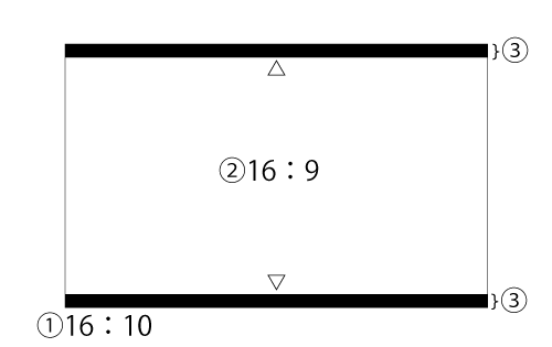
For example, suppose a PICTURE with an ASPECT RATIO of 16:9 is displayed on a screen with an ASPECT RATIO of 16:10.
① The screen ASPECT RATIO is 16:10.
② The PICTURE ASPECT RATIO is 16:9.
③ Use the Vertical Raster Position to move the PICTURE in the Vertical Direction and adjust the DISPLAY area.
b Note
The upper/lower limit depend on signal or aspect ratio.
Blanking
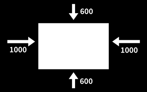
The screen margins can be adjusted vertically by 600 pixels and horizontally 1000 pixels.
| Item | |||
|---|---|---|---|
| Top 600 pixels |
Bottom 600 pixels |
Left 1000 pixels |
Right 1000 pixels |
Press the selector up or down to highlight the desired margin and press left or right to adjust.
Warping & Blending
To perform geometric distortion correction (warping) or to make the seams between images from multiple projectors less noticeable, use the geometric distortion correction and edge blending function.
Press ENTER to display options and then select the desired item.
Warping & Blending Settings
| Setup | Description |
|---|---|
| Off | Disables the geometric distortion correction and edge blending function. |
| On | Enable the geometric distortion correction and edge blending function, and then configure the following: Grid Points, Warp Inner, Warp Sharpness, Grid Color, Grid Background, and Blend Settings. |
| Application | Use the Application to configure geometric distortion correction and Blend Settings. |
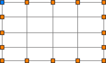
- Grid Points
: Select the number of grid cells.
| Item | ||||
|---|---|---|---|---|
| 2x2 | 3x3 | 5x5 | 9x9 | 17x17 |
5x5
|
|---|
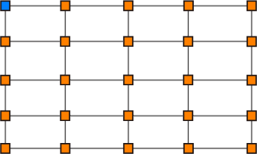
- Warp Inner
: Set to On to Add Point for adjustment inside the grid cells.
| Item | |
|---|---|
| On | Off |
- "Press the selector up, down, left, or right to highlight the desired grid point that you want to modify."
- Press the selector left or right to modify the desired grid point.
|
|---|
- Warp Sharpness
: Adjusts the sharpness during geometric distortion correction.
| Item | |
|---|---|
| 0–19 | |
- Grid Color
: Selects the grid color.
| Item | |||||
|---|---|---|---|---|---|
| White | Red | Green | Blue | Magenta | Cyan |
- Grid Background
: Selects the background color for the grid.
| Item | |
|---|---|
| Black | Transparent |
- Edge Blend Settings
: This function smooths the seams between images from multiple projectors to make them less noticeable.
Press ENTER to display options and then select the desired item.
- Blend Width: Sets the width of the blend area. "There are four options on blend width: up, down, left, and right." The adjusting unit is 4 pixels per step.
- overlap grid count: Select the number of grid lines per Blend Width to be displayed on the grid point screen from 4 / 6 / 8 / 10 / 12.
- Gamma: Specifies the gamma value for the overlapping areas within the range of 1.8–2.4. - Memory
: Saves up to five geometric distortion correction & Edge Blend Settings.
Press ENTER to display options and then select the desired item.- Select Select Memory and press ENTER. Select the desired memory from Memory 1 through Memory 5 as needed.
- Select any of the following items:
- Load: Loads the geometric distortion correction and edge blending settings from the selected memory.
- Save: Saves the geometric distortion correction and edge blending settings to the selected memory.
- Clear: Clears the contents of the selected memory. - Selecting All Clear will clear the contents of all memories.
- Reset
: To reset geometric distortion correction & Blend Settings to the Default Value, press Enter and select Reset when the confirmation screen is displayed.
Keystone
Unavailable when Geometric Distortion Correction & Blend Settings are set to On or Application.
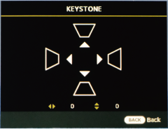
Corrects trapezoidal distortion (keystone adjustment) that occurs when the image is not projected perpendicular to the Screen.
Press the Enter button to display the keystone correction screen, and use the selector (up/down/left/right) button to correct trapezoidal distortion.
Negative values reduce the size of the projected image while positive values increase it.
| Axis | Range |
|---|---|
| Vertical (V) | -60 ~ 0 ~ 60 |
| Horizontal (H) | -60 ~ 0 ~ 60 |
Corner Fit
Unavailable when Geometric Distortion Correction & Blend Settings are set to On or Application.
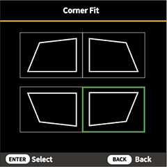
Adjust the Four Corners of the PICTURE individually to ensure the image is free of distortion.
| Item | Range |
|---|---|
| Top Left | Vertical: 0 ~ 80 |
| Horizontal: 0 ~ 120 | |
| Top Right | Vertical: 0 ~ 80 |
| Horizontal: 0 ~ 120 | |
| Bottom Left | Vertical: 0 ~ 80 |
| Horizontal: 0 ~ 120 | |
| Bottom Right | Vertical: 0 ~ 80 |
| Horizontal: 0 ~ 120 |
-
Press the ENTER button to display the Corner Fit screen.
-
Use the selector (up/down/left/right) button to select the area to be corrected, then press the ENTER button.
-
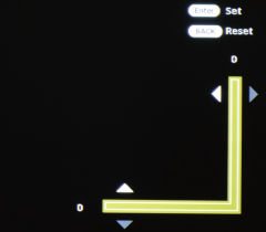
Position the corner horizontally and vertically.
-
Position the corner horizontally and vertically.
Pincushion
Unavailable when Geometric Distortion Correction & Blend Settings are set to On or Application.
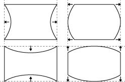
Adjusts images that have barrel distortion or pincushion distortion.
| Item | Range |
|---|---|
| Horizontal | 0~50~100 |
| Vertical | 0~50~100 |