 .
.Warping (Geometric Correction)
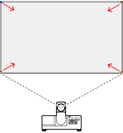
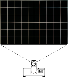
Correct for warping when images are projected onto curved or other irregular surfaces.
Follow the steps below.
-
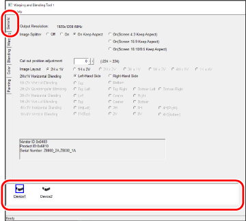
In the Generic tab, select the projector to which settings will be applied.
-
Warping options will be displayed.
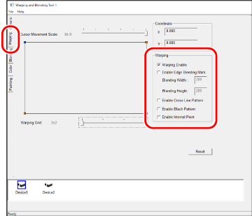
Warping Enable Enable warping. Enable Edge blending mark Display edge blending marks together with the blending width and height. Use this option to choose the edge blending position when warping is enabled. The values for Blending Width and Blending Height are adjusted using edge blending (aBlending (Edge Blending) ). Enable Cross Line Pattern Project a grid pattern as a guide to warping. The input image will not be displayed. Enable black Pattern Select this option for a solid black display. The input image will not be displayed. Enable Internal Point Select this option to add adjustment points inside the grid squares. Select points with the mouse and use the up, down, left, and right arrows on the computer keyboard to adjust the projected image. -
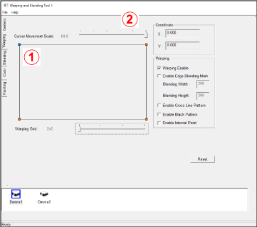
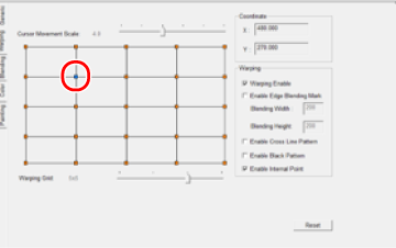
Click the desired adjustment (correction) point in the warping display.
Adjustments are made using the up, down, left, and right arrows on the computer keyboard.
Example
-
ASelect the desired point using the mouse.
-
BChoose the amount of adjustment applied with each key press.
-
CUse the up, down, left, and right arrows on the computer keyboard to adjust the projected image.
The changes made by moving the blue point are visible in the projected image. The image in the warping tool display does not change.
bTIP
Geometric correction applies within the frame. Points cannot be moved outside the boundaries of the frame.
-
Cursor Movement Scale
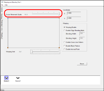
Choose the amount the selected adjustment point (shown in blue) moves with each key press. The amount can be varied by up to six levels.
| Amount (pixels) | |||||
|---|---|---|---|---|---|
| 0.5 | 1.0 | 4.0 | 16 | 32 | 64 |
Warping Grid
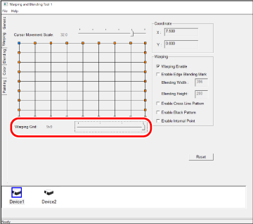
Choose the number of grid squares available for selection.
| Options | |||
|---|---|---|---|
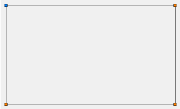
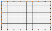
| 2×2 | 3×3 | 5×5 | 9×9 |
2×2
9×9
Coordinate
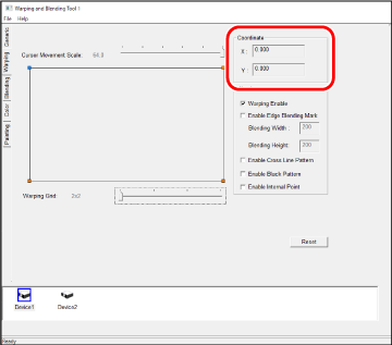
The coordinates of the selected adjustment point (shown in blue).
Warping
Select adjustment points and position them using the up, down, left, and right arrows on the computer keyboard. Repeat for all the desired points.
You will need to select an adjustment point anew after moving the Cursor movement scale or Warping Grid sliders.
bTIP
Start with a warping grid with fewer squares before increasing the square count. Settings applied with lower square counts take priority.
Example: If you make adjustments with a 9 × 9 grid before making adjustments with a 2 × 2 grid, the adjustments made with the 2 × 2 grid will take priority.
dCAUTIONS: Saving Warping Settings
- Before saving warping settings, be sure that Warping Enable is checked.
- Warping settings can be saved in CSV format using the Save as option in the File menu. Name the file as desired.
- Settings for each connected projector must be saved separately. You will also need to load a separate saved CSV settings file for each projector.
- More information on saving settings is available in a“Saving Project Info“.
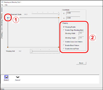
AMove the blue point to correct for warping.
- The changes are visible in the projected image.
- The image in the warping tool display does not change.
BWarping options
Warping Options
- Warping Enable: Enable warping.
-
Enable Edge blending mark: Display edge blending marks together with the blending width and height.
- Blending Width: The amount, in pixels, by which the projected images overlap horizontally.
- Blending Height: The amount, in pixels, by which the projected images overlap vertically.
The values can be adjusted using edge blending (aBlending (Edge Blending) ).
-
Enable Cross Line Pattern: Select this option to display a grid on the projection screen. The input image will not be displayed.
-
Enable black Pattern: Select this option for a solid black display. The input image will not be displayed.
-
Enable Internal Point: Select this option to add adjustment points inside the grid squares.
Select points with the mouse and use the up, down, left, and right arrows on the computer keyboard to adjust the projected image.
The change made, for example, by pressing the right arrow on the computer keyboard when a dot is selected will be visible in the projected image.

Reset
Reset all adjustments to their default values. For information on saving current settings, see a “Saving Project Info”.