 .
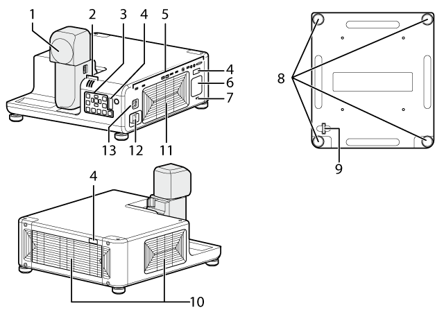
.Parts of the Projector: Names and Functions
| Item | Name |
|---|---|
| 1 | Lens |
| 2 | Indicator lamps |
| 3 | Control panel |
| 4 | Remote receiver |
| 5 | Interface (connector) panel |
| 6 | Speaker |
| 7 | Security slot * |
| Item | Name |
|---|---|
| 8 | Adjustable feet |
| 9 | Security lock |
| 10 | Intake vents |
| 11 | Exhaust vent |
| 12 | Power connector |
| 13 | Main power |
* Compatible with Kensington MicroSaver security system locks.
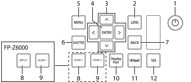
Control panel
Basic operations are performed using the control panel. The names and functions of the buttons on the control panel are given below.
| Item | Button | Function |
|---|---|---|
| 1 |
Turn the projector on or switch it to standby. The projector automatically switches to standby about three seconds after the lens is returned to the storage position. |
|
| 2 | LENS | Adjust lens focus, shift, and zoom. |
| 3 | Selector | Navigate the menus. |
| 4 | ENTER | Select the highlighted menu item. |
| 5 | MENU | Display the menus used to adjust projector settings. |
| 6 | SHUTTER | Temporarily suspend projection and mute audio. Press again to resume. |
| 7 | BACK | Return to the previous menu. |
| 8 | HDMI1 | Select HDMI 1 (FP-Z8000). |
| INPUT | Select an input source (FP-Z6000). | |
| 9 | HDMI2 | Select HDMI 2 (FP-Z8000). |
| HDMI1 | Select HDMI 1 (FP-Z6000). | |
| 10 | DisplayPort | Select DisplayPort. |
| 11 | HDBaseT | Select HDBaseT. |
| 12 | SDI | Select SDI. |
The Arm and Head Latches
The lens can be rotated and is equipped latches for the arm and projector head. Rotate the lens as described below. Be sure to latch the lens while projector is in use.
dCAUTIONS
- Some portions of the projected image may not be visible depending on lens shift and the orientation of the lens.
- When rotated, the lens automatically returns to the previous shift position, causing the picture move. Do not rotate the lens while lens shift is in progress (i.e., while the image is moving).
- When rotating the lens, keep it supported and rotate it slowly.
- Pay attention to your surroundings when rotating the lens. Light from the product projected into the eyes could cause visual impairment.
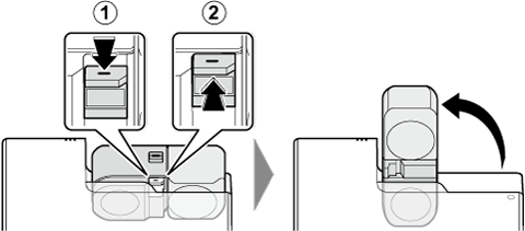
Rotating the Arm
When the arm latch is disengaged by pressing the arm latch release, the arm can be rotated 90°. Lift the latch release to latch the arm once more.
AUnlatch
BLatch
Rotating the Projector Head
When the head latch is disengaged by sliding the head latch release to the FREE position, the projector head can be rotated 360° in 90° increments.
AFREE position
BLOCK position
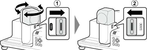
The lens can be rotated when the head latch release is in the FREE position and latches when the release is in the LOCK position.
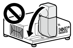
dCAUTION
Do not return the arm to the storage position with the lens facing down. Failure to observe this precaution could scratch or break the lens.
dCAUTION: TRANSPORT AND STORAGE
Observe the following precautions to prevent the lens being scratched or broken during transport and storage.
- Return the lens to the home lens shift position. (
 : Hold the SHIFT button for 3 seconds.)
 - Be sure to return the lens to the storage position.
-
Attach the two protective covers (one large and one small) to the lens for transport.
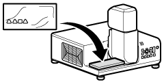
Large cover
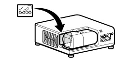
Small cover
Connectors
Connect devices to the connectors using the appropriate cables.

| Connector | Description | ||
|---|---|---|---|
| Video IN | 1 | HDMI 1 IN | HDMI 2.0 (compatible with HDCP 2.2, accepts 3840 × 2160 60P input) |
| 2 | DisplayPort IN | Display Port1.2 (compatible HDCP 1.3, accepts 3840 × 2160 60P input) | |
| 3 | SDI IN | BNC (3G/HD/SD SDI input) | |
| 4 | HDBaseT IN | RJ-45 for video/audio/connection control (accepts 3840 × 2160 60P input) | |
| Control IN/OUT | 5 | LAN | RJ-45 for network connection (10Base-T/100Base-TX) |
| 6 | HDBaseT IN | RJ-45 for projector connection control | |
| 7 | RS‑232C IN | D-Sub 9 pin for projector connection control | |
| Audio IN/OUT | 8 | AUDIO IN | 3.5 mm stereo mini jack |
| 9 | AUDIO OUT | 3.5 mm stereo mini jack | |
| Other | 10 | USB 1 | Type A for maintenance, DC 5V 1.5A (Max) |
| Warping/edge blending function *1 (FP-Z8000 only) |
11 | HDMI 2 IN *2 | HDMI 1.4 (compatible with HDCP 1.4, audio input not supported) |
| 12 | USB 2 | Type A for warping/edge blending function | |
For information on connecting cables, see a “Connections”.
Input selection is made via software. At default settings, the input signal resolution is fixed at 1920 × 1200. Input at resolutions other than the selected value may produce unexpected results.
dCAUTIONS
- Before connecting cables, switch the projector to standby and confirm that the peripheral is either off or in standby mode. After connecting the cable to both devices, turn the projector on first and then turn on the peripheral.
- Some devices require an adapter and/or a dedicated cable.
Indicator Lamps
Projector status is shown by whether the indicator (ON/STANDBY, TEMP, and STATUS) lamps are on, flashing, or off.
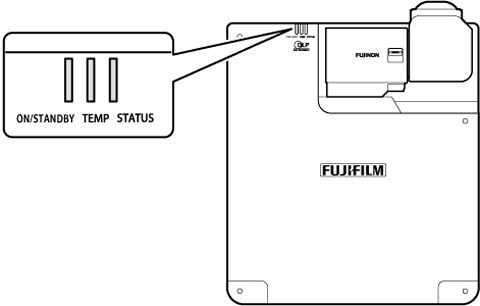
The statuses shown by the condition of the indicator lamps are listed below.
| Lamp | |||
|---|---|---|---|
| ON/STANDBY | TEMP | STATUS | Projector status |
| On (red) | Off | Off | Projector in standby mode. |
| Flashing (red) | Off | Off | Projector in network standby mode. |
| flashing (green) | Off | Off | Launching. |
| On (green) | Off | Off | Projector on. |
| On (green) or flashing (green) | Flashing (red) | Off | Projector temperature elevated. |
| Off | Off | On (red) or Flashing (red) | Problem with cooling fan. |
| On (green) or flashing (green) | Off | On (red) or Flashing (red) | |
| flashing (green) | Off | Flashing (red) | Problem with optical engine. |
| Off | On (red) | On (red) or Flashing (red) | Temperature rise in laser light source. |